1. How to create an inbound interface using integrate Autoswitch mode with SKYVVA V3 Connector Module?
This document describes how to create an inbound interface using Integrate AutoSwitch mode with V3 SKYVVA connector module
What is Auto-Switch mode?
Auto-switch mode is a data processing mode provided by SKYVVA. When the auto-switch mode flag checked, It means that Agent automatic switch SKYVVA API based on a number of record and IntegrateMaxSize, IntegrateBatchMaxSize. And when the flag is unchecked it means that data is integrated with normal mode (no batch or bulk) no matter what is the size of records. Before configuring Auto-Switch Mode, you have to know about the parameters:
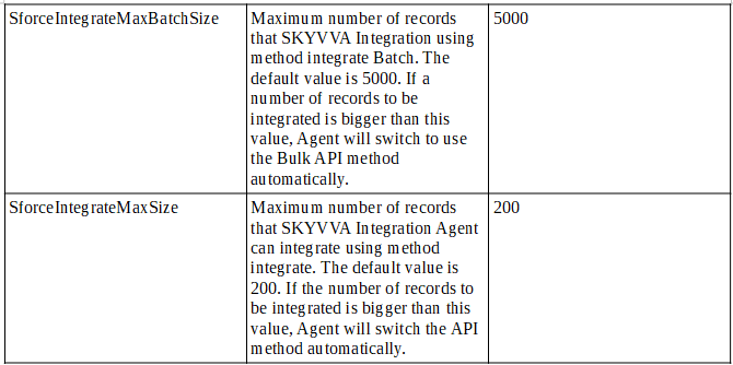
- Integrate Max Size: Maximum number of records that SKYVVA Integration Agent can integrate using method integrate. The default value is 200. If the number of records to be integrated is bigger than this value, Agent will switch the API method automatically.
- Integrate Batch Max Size: Maximum number of records that SKYVVA Integration using method integrate Batch. The default value is 5000. If a number of records to be integrated is bigger than this value, Agent will switch to use the Bulk API method automatically.
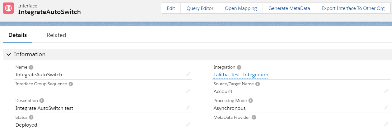
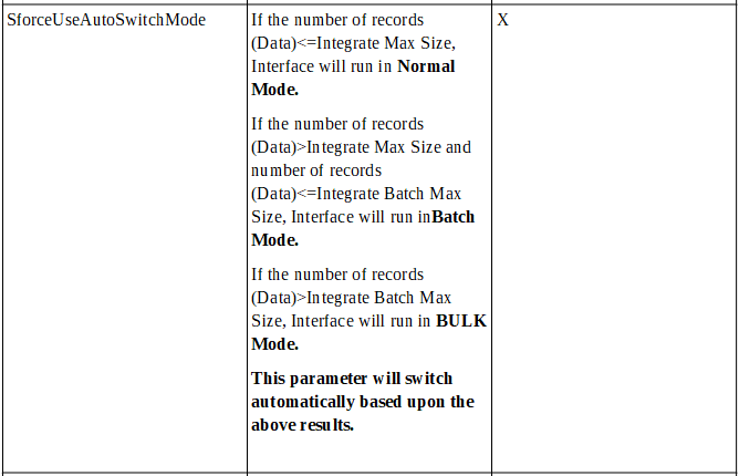
If the number of records (Data) <= Integrate Max Size, Interface will run in Normal Mode. If the number of records (Data) > Integrate Max Size and number of records (Data) <= Integrate Batch Max Size, Interface will run in Batch Mode. If the number of records (Data) > Integrate Batch Max Size, Interface will run in BULK Mode. 2. SKYVVA interface creation Create an interface, for example, "IntegrateAutoSwitch" as shown below.
maximum integrate Batch size will be 5000
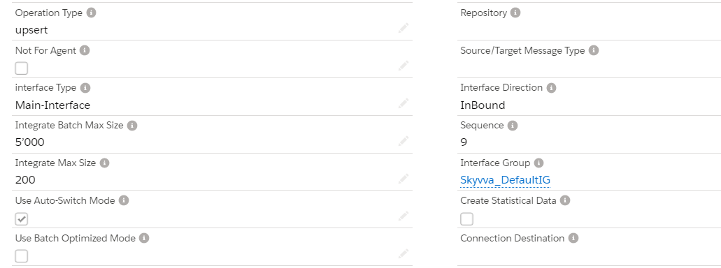
Now save the interface and download the WSDL
Step 3 - Import WSDL into ESR First, we have to create a namespace in ESR like "urn:skyvva:integrateAutoSwitch". Now create an external definition under the namespace like below. Here the WSDL is for Account. So, we can give the name as ED_Account.
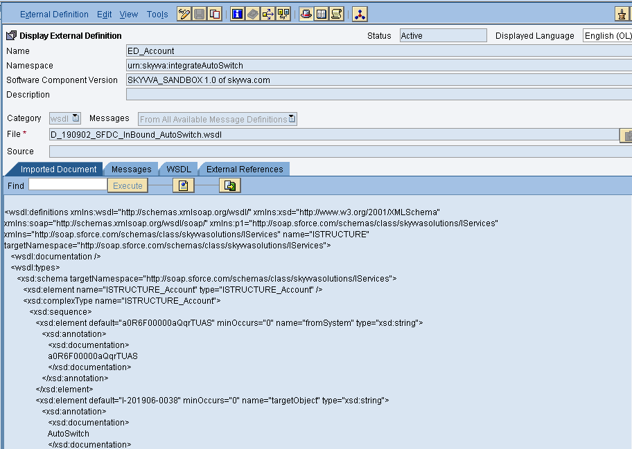
Import the WSDL and save and activate the external definition.
- Sender data type
Create sender data type as shown below
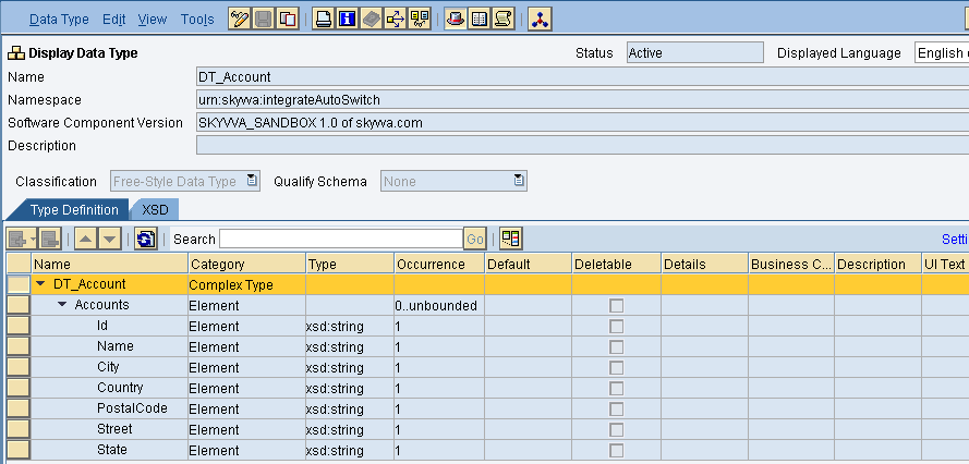
after creating the source data type click on save and activate.
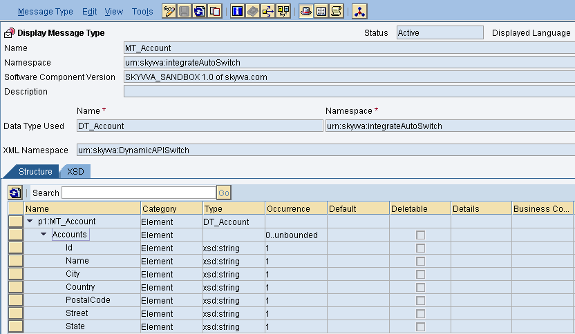
- Source message type
Create the message type as shown below.
- Outbound Service Interface
Create an Outbound service interface, in that select category as outbound and select the respective message type.
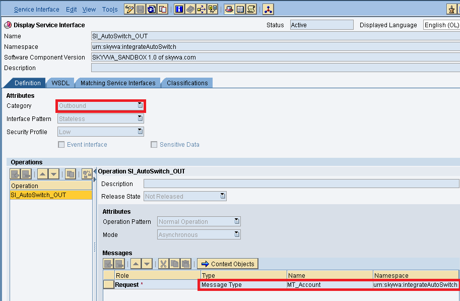
then save and activate the outbound service interface.
- Inbound Service Interface
Create an inbound service interface, in that select category as inbound and select the respective external definition.
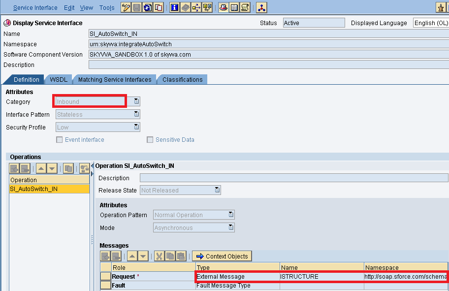
Save and active the inbound service interface.
- Message Mapping
Create message mapping as shown below
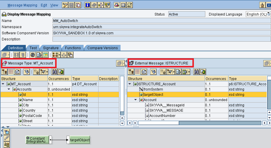
Insert the respective source and target structure and then do the mapping. Now save and activate the message mapping
- Operation Mapping
Create Operation mapping as shown below
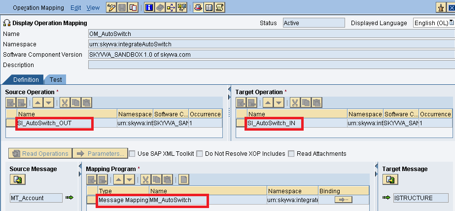
Select the respective outbound and inbound service interfaces and also the message mapping then save and activate the operation mapping. Creation of Integrated Configuration Objects After creating the objects in ESR. We have to configure these objects in the integration directory. First, we have to create Configuration Scenario.
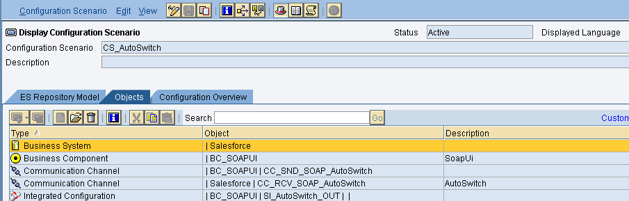
An Integration scenario has the following objects.
- Business System for Sender and Receiver
- Sender and Receiver Communication channel
- Integrated Configuration
These are the objects we should create. We have to define our business system e.g. for the SAP-Backend. For Salesforce you can use our proposal "Salesforce" as the business system. We have to import these business systems from SLD.
Configuring the Sender SOAP communication channel Create sender communication channel as shown below. Since we are using SOAP UI as a source. So, here we are using SOAP in the sender channel.
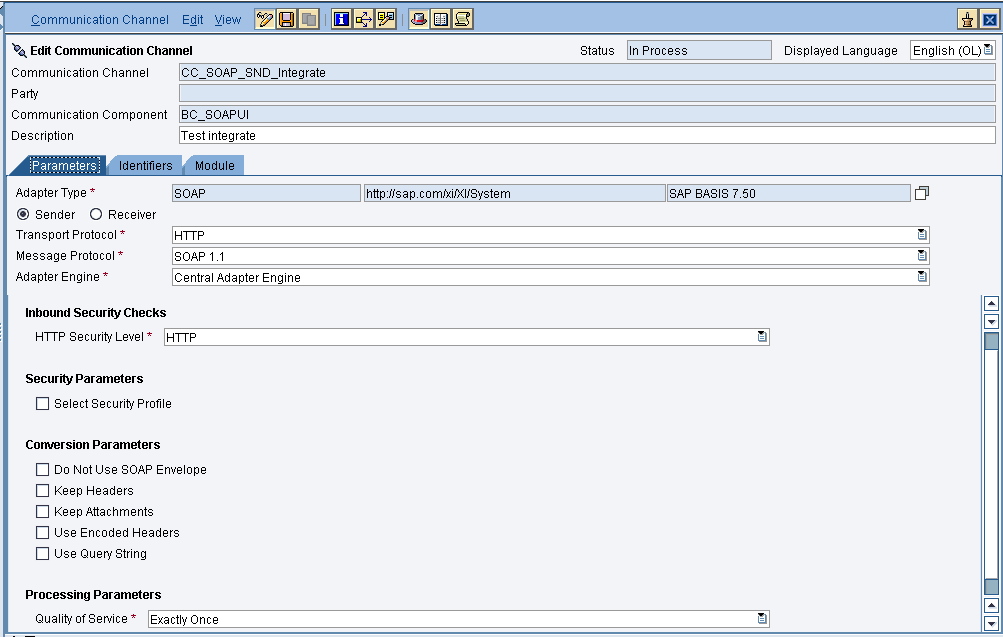
Provide the necessary details as shown and then save and activate the channel.
- Configuring the SOAP receiver channel
Configuration for Tab "General"
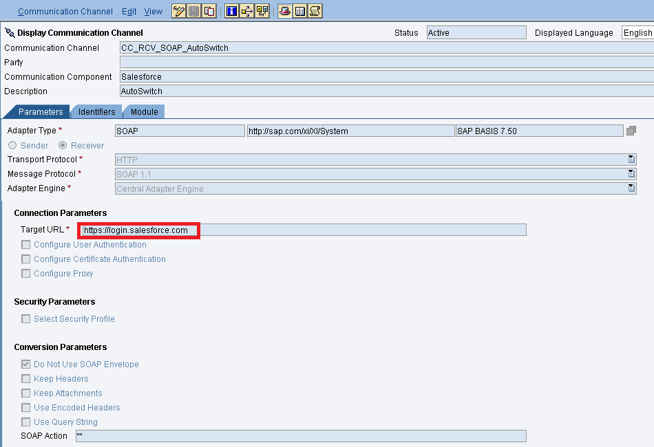
Specify the parameters as shown in the above screenshot. Below is the configuration for the "Advanced" Tab.
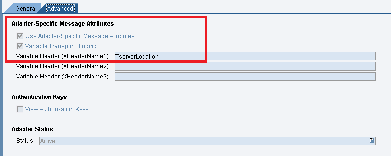
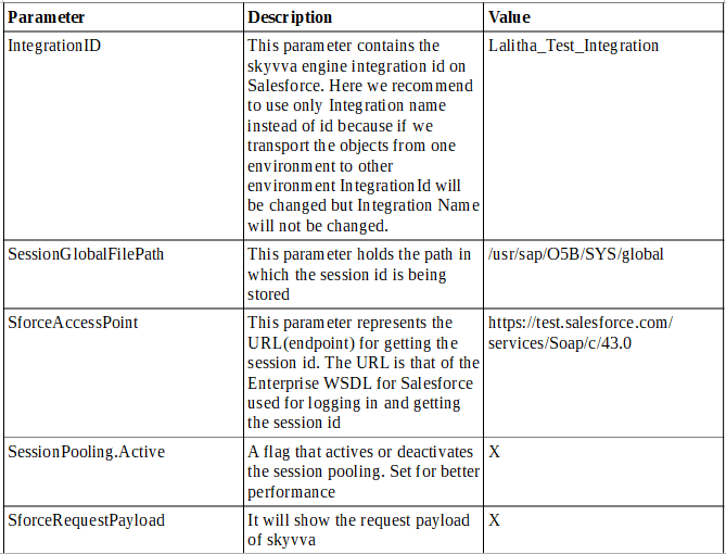
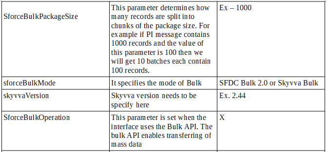
The value "TserverLocation" has to be entered for the parameter Variable Header (XHeaderName1). Below are the settings for Tab "Module". Here, the SKYVVA module containing the logic for session handling must be specified. Skyvva/V3/Integration
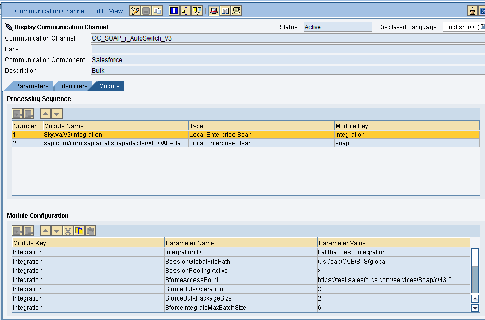
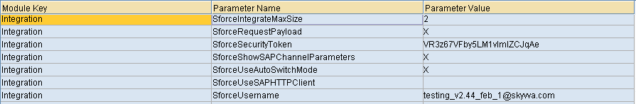

Configuration of module parameters are described in detail below
- SKYVVA Module Parameters
Integrated Configuration Create integrated configuration objects as shown below.
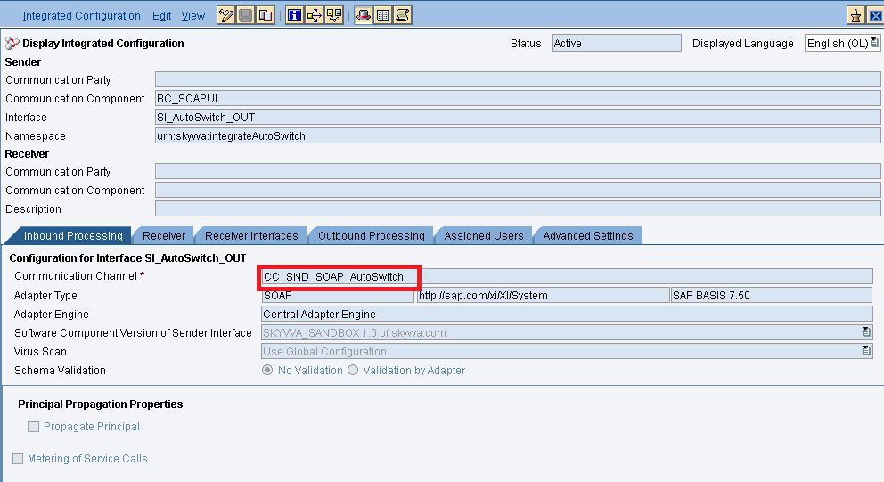
Enter the required data e.g. the Communication Component, Interface and Namespace and then click on create button to create an ICO. Now go through the tabs from left to right to configure the relevant objects. In this first tab “Inbound Processing” here we have to specify the sender communication channel.
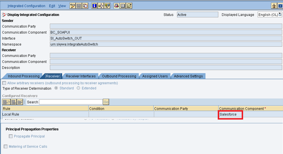
Here in the “Receiver” tab, we have to specify the receiver business system.
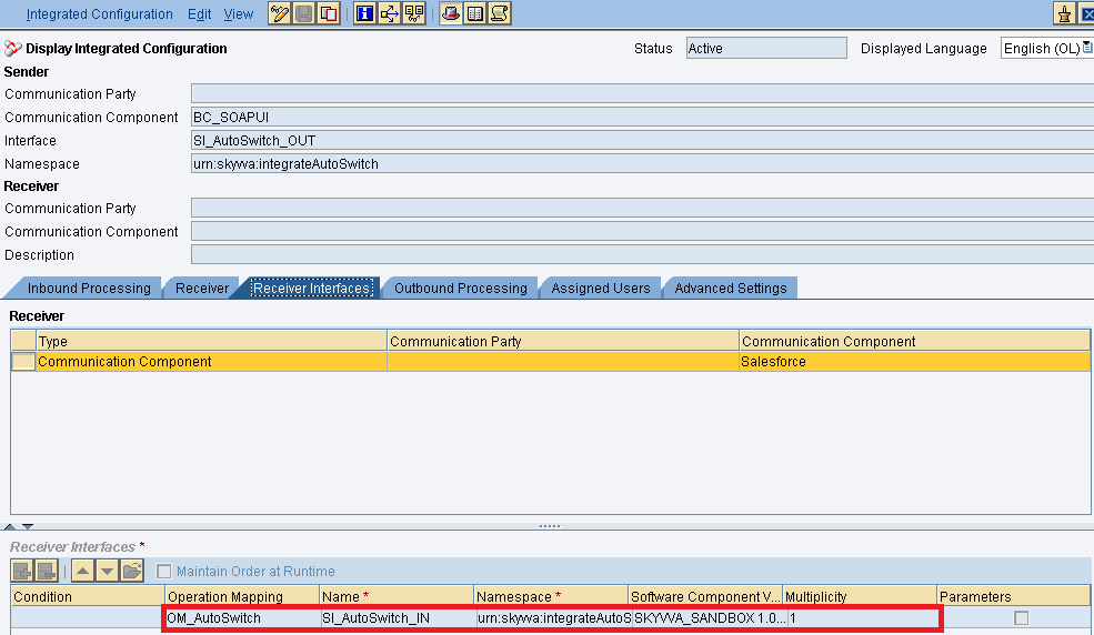
In Receiver interfaces tab specify the operation mapping.
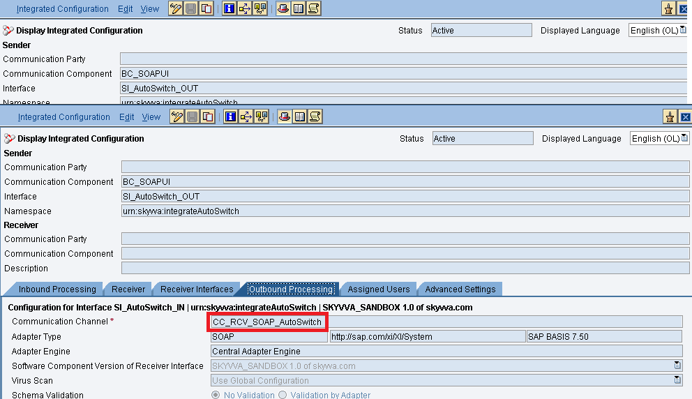
In the “outbound processing” tab, we have to specify the receiver channel.
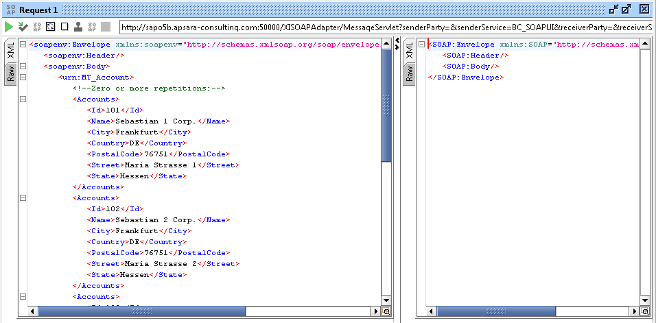
- Testing the Inbound Interface.
Triggering 2 records from the Source SOAP UI.
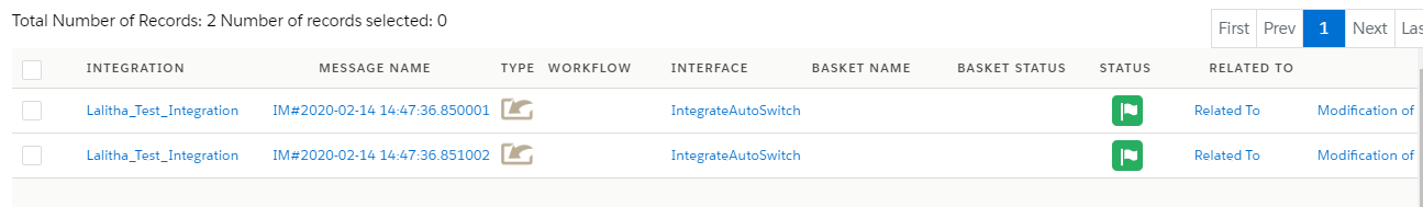
Now we have to check the result in SKYVVA message board as shown below.
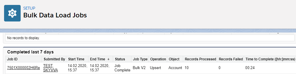
Triggering more than 6 records from SOAP UI. As we are using SFDC Bulk. So we can see the result in SFDC Bulk data loads as shown below